产品中心
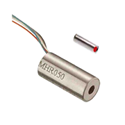
提供精确测量的MHR系列位移传感器

| 介绍: | 传奇的MHR系列LVDTs在空间限制应用中提供精确测量。MHR系列直径仅为3/8英寸(9.5mm),芯极轻,是理想的f。 或者,当过高的堆芯重量会影响被测物体的运动时,用较小的惯性,在较高的位移速度下进行精确的测量就更容易实现了。轻量级c 矿石还减少机械应力,并有助于保持核心驱动组件的结构完整性。线圈与铁芯之间的紧密电耦合所产生的高输出灵敏度为与几乎所有的信号调理器和调理CIRC接口提供了充足的信 |
|---|

传奇的MHR系列LVDTs在空间限制应用中提供精确测量。MHR系列直径仅为3/8英寸(9.5mm),芯极轻,是理想的f。 或者,当过高的堆芯重量会影响被测物体的运动时,用较小的惯性,在较高的位移速度下进行精确的测量就更容易实现了。轻量级c 矿石还减少机械应力,并有助于保持核心驱动组件的结构完整性。
线圈与铁芯之间的紧密电耦合所产生的高输出灵敏度为与几乎所有的信号调理器和调理CIRC接口提供了充足的信号。 尤伊茨。磁性不锈钢外壳提供电磁和静电屏蔽。
高温操作(200 OC)适用于中风范围±0.025~±1英寸(会诊厂)。高压(排气箱)版本也提供(咨询工厂)。MH R与测量专业的全线LVDT信号调理器兼容。
和我们的大多数lvdts一样,mhr绕组是用一种特殊配方的高温柔性树脂进行真空浸渍的,线圈组件在其外壳内装有两个组件。 环氧树脂。这提供了良好的保护,以抵御恶劣环境,如高湿度,振动和冲击。
技术参数

PERFORMANCE SPECIFICATIONS
![]()
ELECTRICAL SPECIFICATIONS (common) | |
Input voltage | 3 VRMS sine wave |
Input frequency | 2kHz to 20kHz |
Test frequency | 2.5kHz (standard) |
ELECTRICAL SPECIFICATIONS @ 10kHz (recommended operation) | |||||||||
Parameter | MHR 005 | MHR 010 | MHR 025 | MHR 050 | MHR 100 | MHR 250 | MHR 500 | MHR 1000 | MHR 2000 |
Stroke range | ±0.005 [±0.13] | ±0.010 [±0.25] | ±0.025 [±0.64] | ±0.05 [±1.27] | ±0.10 [±2.54] | ±0.25 [±6.35] | ±0.5 [±12.7] | ±1 [±25.4] | ±2 [±50.8] |
Sensitivity V/V/inch [mV/V/mm] | 8.70 [343] | 6.05 [238] | 8.10 [319] | 3.15 [124] | 2.80 [110] | 2.07 [81.5] | 1.96 [77.2] | 0.77 [30.3] | 0.49 [19.3] |
Output at stroke ends mV/V (*) | 43.5 | 60.5 | 202.5 | 157.5 | 280 | 517.5 | 980 | 770 | 980 |
Phase shift | +38° | +20° | +21° | +8° | +5° | +7° | +7° | -1° | -15° |
Input impedance (PRIMARY) | 84Ω | 165Ω | 238Ω | 419Ω | 400Ω | 345Ω | 264Ω | 155Ω | 504Ω |
Output impedance (SECONDARY) | 302Ω | 300Ω | 485Ω | 154Ω | 200Ω | 420Ω | 810Ω | 450Ω | 1780Ω |
Non-linearity | ±% of FR | ||||||||
@ 50% stroke | 0.20 | 0.10 | 0.15 | 0.15 | 0.15 | 0.15 | 0.15 | 0.20 | / |
@100% stroke (max) | 0.25 | 0.25 | 0.25 | 0.25 | 0.25 | 0.25 | 0.25 | 0.25 | 0.50 |
@125% stroke | 0.30 | 0.35 | 0.25 | 0.35 | 0.25 | 0.35 | 0 .30 (**) | 0 .50 | / |
@150% stroke | 0.40 | 0.35 | 0.30 | 0.50 | 0.30 | 0.50 (**) | 0.75 (**) | / | / |
Null voltage (max.) | 2.5% FRO | 1.0% FRO | 0.5% of FRO | ||||||
(*) Unit for output at stroke ends is millivolt per volt of input voltage; (**) Requires special reduced core length
ELECTRICAL SPECIFICATIONS @ 2.5kHz (standard calibration) | |||||||||
Parameter | MHR 005 | MHR 010 | MHR 025 | MHR 050 | MHR 100 | MHR 250 | MHR 500 | MHR 1000 | MHR 2000 |
Stroke range | ±0.005 [±0.13] | ±0.010 [±0.25] | ±0.025 [±0.64] | ±0.05 [±1.27] | ±0.10 [±2.54] | ±0.25 [±6.35] | ±0.5 [±12.7] | ±1 [±25.4] | ±2 [±50.8] |
Sensitivity V/V/in [mV/V/mm] | 3.19 [126] | 3.36 [132] | 4.36 [172] | 2.55 [100] | 2.40 [94] | 1.73 [68] | 1.60 [63] | 0.70 [27] | 0.47 [19] |
Output at stroke ends, mV/V (*) | 16 | 33.6 | 109 | 127.5 | 240 | 432.5 | 800 | 700 | 940 |
Phase shift | +73° | +59° | +58° | +36° | +30° | +33° | +23° | +6° | +3° |
Input impedance (PRIMARY) | 59Ω | 78Ω | 116Ω | 141Ω | 135Ω | 147Ω | 145Ω | 100Ω | 304Ω |
Output impedance (SECONDARY) | 260Ω | 192Ω | 286Ω | 90Ω | 125Ω | 268Ω | 445Ω | 370Ω | 13620Ω |
Non-linearity | ±% of FR | ||||||||
@ 50% stroke | 0.20 | 0.10 | 0.15 | 0.15 | 0.15 | 0.15 | 0.15 | 0.20 | / |
@100% stroke (max) | 0.25 | 0.25 | 0.25 | 0.25 | 0.25 | 0.25 | 0.25 | 0.25 | 0.25 |
@125% stroke | 0.30 | 0.35 | 0.25 | 0.35 | 0.25 | 0.35 | 0.30 (**) | 0 .50 | / |
@150% stroke | 0.40 | 0.35 | 0.30 | 0.50 | 0.30 | 0.50 (**) | 0.75 (**) | / | / |
Null voltage (max) | 3% FRO | 1.5% FRO | 0.5% of FRO | ||||||
(*) Unit for output at stroke ends is millivolt per volt of input voltage; (**) Requires special reduced core length
ENVIRONMENTAL SPECIFICATIONS & MATERIALS | |
Operating temperature | -65°F to +300°F [-55°C to 150°C] |
Shock survival | 1,000 g (11ms half-sine) |
Vibration tolerance | 20 g up to 2KHz |
Housing material | AISI 400 Series stainless steel |
Electrical connection | Six lead-wires, 32 AWG stranded Copper, PTFE insulated, 1 foot [0.3m] long (longer wires optional) |
IEC 60529 rating | IP61 |
Notes:
All values are nominal unless otherwise noted
Electrical specifications are for the test frequency indicated in the table Dimensions are in inch [mm] unless otherwise noted
FR: Full Range is the stroke range, end to end; FR=2xS for ±S stroke range
FRO (Full Range Output): Algebraic difference in outputs measured at the ends of the range
MECHANICAL SPECIFICATIONS
![]()
Parameter | MHR 005 | MHR 010 | MHR 025 | MHR 050 | MHR 100 | MHR 250 | MHR 500 | MHR 1000 | MHR 2000 |
Body length “A” | 0.375 [9.5] | 0.535 [13.6] | 0.660 [16.8] | 0.815 [20.7] | 0.990 [25.1] | 1.850 [47.0] | 3.300 [83.82] | 5.600 [142.2] | 8.000 [203.2] |
Core length “B” | 0.180 [4.6] | 0.233 [5.9] | 0.400 [10.2] | 0.500 [12.7] | 0.625 [15.9] | 1.125 [28.6] | 2.000 [50.8] | 3.000 [76.2] | 3.00 [76.2] |
Body weight oz [g] | 0.07 [2] | 0.11 [3] | 0.18 [5] | 0.21 [6] | 0.21 [6] | 0.32 [9] | 0.60 [17] | 0.92 [26] | 1.4 [40] |
Core weight oz [g] | 0.004 [0.1] | 0.007 [0.2] | 0.016 [0.5] | 0.016 [0.5] | 0.025 [0.7] | 0.032 [0.9] | 0.056 [1.6] | 0.088 [2.5] | 0.088 [2.5] |


